When we transfer data, there are a few things that we need to consider to ensure that our transfers are quick, lossless, and efficient. However, transmitting data requires bandwidth.
Or let us put it in even simpler terms. From a layman perspective, if we have a high number of connections or wires between two points, you can transfer a more massive amount of data. However, transmission lines, connections, even the traces on a circuit board are an expensive commodity — both cost and real estate wise.
You ideally need a system where you can transfer the most data using the least connections and cost. That is one of the core aspects of communication system design.
Multiplexing is a concept that is very important in this aspect. Multiplexing means to transmit more than one signal on a single transmission line.
In this post, we will look at the multiplexer and demultiplexer circuits. We will also tabulate the multiplexer and demultiplexer truth tables.
Contents
What is a multiplexer?
A multiplexer is a digital combinational logic circuit with n inputs and one output. Its purpose is to connect one of the inputs to the output line, depending on a control signal. The general symbol of a multiplexer is shown below.
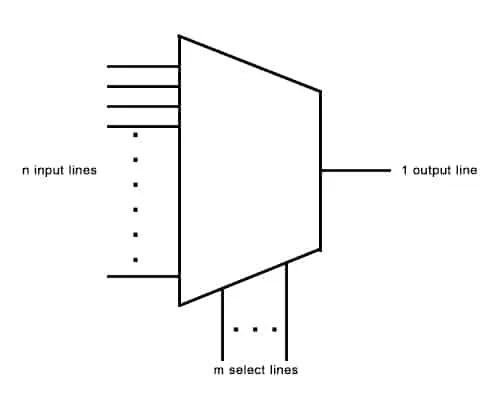
Basically, it switches between one of the many input lines and connects them one by one to the output. It decides which input line to switch to using a control signal.
Physically, a multiplexer has n input pins, one output pin, and m control pins. n = 2^m. We can refer to a multiplexer with the terms MUX and MPX too. Since a multiplexer’s job is to select one of the data input lines and send it to the output, it is also known as “data selector.”
There are three main ways of constructing a multiplexer.
- Digital multiplexers, which are the focus of our post, are made up of logic gates.
- Analog multiplexers are made using transistors.
- Mechanical switches, which are also known as rotary switches, are made using rotating shafts.
The mux itself acts like a digitally controlled multi-position switch where the binary code applied to the select inputs controls the data input, which will be switched to the output.
How does a multiplexer work?
To understand the design and working of a multiplexer, we will dive right in. We will start by designing the simplest of digital multiplexers: the 2:1 mux.
For a 2:1 mux, we have two input lines, one select line (2^x = 2, then x=1) and one output line. Since we have one control input, there are only two possible values for it. 0 and 1. When the control input is 0, the first input line connects to the output. When the control output is 1, the second input line connects to the output. So now you understand how a control line controls which input connects to the output.
2:1 multiplexer truth table
| I0 | I1 | S | Output |
| 0 | 0 | 0 | 0 |
| 0 | 0 | 1 | 0 |
| 0 | 1 | 0 | 0 |
| 0 | 1 | 1 | 1 |
| 1 | 0 | 0 | 1 |
| 1 | 0 | 1 | 0 |
| 1 | 1 | 0 | 1 |
| 1 | 1 | 1 | 1 |
From the k-map of the above truth table we get
Output = SI1 + S’I0

As we can see in the multiplexer circuit, depending on the value of the select line (S), we can select an input line to connect it to the output. The current value on the line that is selected passes to the output.
In this way, the multiplexer acts as a switching circuit. Now, as we increase the number of inputs, the number of select lines will increase too.
Let’s now design a 4:1 multiplexer circuit.
Can you calculate how many select lines would be present in this mux?
We have four inputs, what number of digits in a binary number gives you four possible combinations? Or, using how many digits in a binary number can you count up to four?
If you are unable to answer these questions, you still have the formula we saw above to count on. For n inputs, m select lines, where n=2^m. 4 = 2^m, therefore, m =2. We need two select lines for a 4:1 mux.
4:1 multiplexer truth table
| I0 | I1 | I2 | I3 | S0 | S1 | Output |
| 0 | x | x | x | 0 | 0 | 0 |
| 1 | x | x | x | 0 | 0 | 1 |
| x | 0 | x | x | 0 | 1 | 0 |
| x | 1 | x | x | 0 | 1 | 1 |
| x | x | 0 | x | 1 | 0 | 0 |
| x | x | 1 | x | 1 | 0 | 1 |
| x | x | x | 0 | 1 | 1 | 0 |
| x | x | x | 1 | 1 | 1 | 1 |
x is don’t care because that particular line is not selected by the control lines’ values.
When
S0S1 = 00 (0 – decimal value), I0 is connected to the output.
S0S1 = 01 (1), I1 is the output.
S0S1 = 10 (2), I2 is the output
S0S1 = 11 (3), I3 is the output
Solving for output using the method we saw in the post for comparators. Output is 1 when I0 = 1 and S0 = 0 and S1 = 0 OR when I1 = 1 and S0 = 0 and S1 = 1 and so on we get
Output = I0S0’S1′ + I1S0’S1 + I2S0S1′ + I3S0S1
Plotting the circuit for the above equation we get the following logic circuit for a 4:1 multiplexer.

What are the uses of a multiplexer?
The applications of a multiplexer include
- In a communication system where we have a communication network, a multiplexer increases the efficiency of the system by allowing the transmission of audio and video data on a single channel.
- In optical fiber communication, a multiplexer does the same job to combine multiple fiber cables onto one fiber cable using a technique called Dense wavelength division multiplexing.
- In satellite communication, multiplexers transfer data from the satellite’s computer system to the ground segment using GSM communication.
- It also works as a parallel to serial data converter.
- In a computer, it decreases the number of copper lines necessary to connect the memory to other parts of the computer.
How to join multiplexers?
If we have small multiplexers, but we wish to increase their functionality, we can join them to obtain a mux with more inputs. The cascading of multiplexers is easy. You just need to make sure that you connect in a way that gives the same number of inputs and control lines as your target mux.
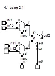
Let’s make a 4:1 mux using 2:1 multiplexers. We know that a 2:1 mux has two inputs and one select line. So joining two 2:1 multiplexers will give us four inputs, two outputs (we need only 1), and two select lines. So how do we proceed?
If we can somehow reduce the outputs to one, it would be really easy. Since we wish to use only multiplexers, how do we combine two lines to get a single line?
We use another 2:1 mux!
However, though that gives us the one output that we require, it gives us an additional select line. So now we have three select lines.
How do you reduce three select lines to two select lines?
If only we could just remove one select line. Well, we can do that by joining two select lines. That would essentially reduce the two lines to one single line. This is the result we get by applying our logic.
How to design 8:1 multiplexer, 16:1 multiplexer, and so on?
Similar to the process we saw above, you can design an 8 to 1 multiplexer using 2:1 multiplexers, 16:1 mux using 4:1 mux, or 16:1 mux using 8:1 multiplexer. Try designing these using only multiplexers using similar logic to the one we saw above. Cross-check your answers with the designs below.

You can also go the opposite way and use a multiplexer with more inputs than required as a smaller mux. Here’s an 8:1 multiplexer being used as a 2:1 multiplexer.

How to make logic gates using multiplexers?
Since the logic gates we study are generally with two inputs and have one output, we can take it up as a logical challenge to design all logic gates using a 2:1 multiplexer.
As with a lot of logical circuits, making gates using mux also does not have a method written in stone. You can try alternative designs and arrive at the same logical conclusions.
Let’s start with the NOT gate. We know that it just inverts the input and has one input. If we consider the select line to be the input, apply a HIGH logic at Io, and LOW logic at I1, we get a NOT gate.

Similarly, by applying some logic, you can derive all other gates using just 2:1 Mux. Try it! It’s a good exercise for increasing logical ability.

What is a demultiplexer?
A demultiplexer is a combinational logic circuit that performs the opposite function as that of a multiplexer.
In a demux, we have n output lines, one input line, and m select lines. The relation between the number of output lines and the number of select lines is the same as we saw in a multiplexer. That is, 2^m = n. Depending on the value of the binary number formed by the select lines, any one of the output lines connects to the input line.
The rest of the output lines at this point go to an OFF state. That is, the value of the remaining lines is 0.
In this way, a demultiplexer converts serial data to parallel data and acts as a serial-parallel converter. Moreover, since it connects one data line to multiple data lines and switches between them, a demultiplexer is also known as a “data distributor.” A demultiplexer is alternatively referred to as a demux.
The general symbol of a demultiplexer is shown below.

How does a demultiplexer work?
To understand the working of a demultiplexer, we will straight away design one. The 1:2 demux is the simplest of all demultiplexers. We have one input, two outputs, and one select line (2^m = 2, therefore m=1). Let’s write the truth table for this demux.
1:2 demultiplexer truth table
| I0 | S | Y0 | Y1 |
| 0 | 0 | 0 | 0 |
| 0 | 1 | 0 | 0 |
| 1 | 0 | 1 | 0 |
| 1 | 1 | 0 | 1 |
From the truth table
Y0 = I0S’ and
Y1 = I0S
The resulting circuit of a 1:2 demultiplexer using logic gates using the equations we got from the truth table is shown below.

As you can see, depending on the value of the select line, one of the output connects to the input line. When S is 0, the first output line connects to the input. When S is 1, the second output line connects to the input.
In this way, a demultiplexer distributes data from one data line to multiple data lines.
Next, we will design a 1:4 demultiplexer. From the formula for select lines we saw above, a 1:4 demux will have two select lines. Let’s draw the truth table for a 1:4 demux.
Truth table for a 1:4 demultiplexer
| I0 | S0 | S1 | Y0 | Y1 | Y2 | Y3 |
| I | 0 | 0 | I | 0 | 0 | 0 |
| I | 0 | 1 | 0 | I | 0 | 0 |
| I | 1 | 0 | 0 | 0 | I | 0 |
| I | 1 | 1 | 0 | 0 | 0 | I |
As you can see, this truth table is shorter than the one for the 4:1 mux. This is because instead of taking both the possible values of the input, we just took it as I. The resulting equations will be the same. When you have large truth tables, tricks like this are handy and will make it easier for you to get to the equations you need.
So from the truth table,
Y0 = S0’S1′
Y1 = S0’S1
Y2 = S0S1′
Y3 = S0S1
The resultant circuit for the above equations is shown below.
What are the applications of a demultiplexer?
- In a communication system, a demultiplexer can receive serial data from a multiplexer that is present at the transmission end. The demux then converts the data into its original form.
- We can store an ALU’s output in multiple memory registers using a demultiplexer.
- The demultiplexer also acts as a serial to parallel converter.