In this post, we will learn the basics of electronic logic gates. We will see their working and truth tables. We will also gander over the implementation of all basic logic gates using universal gates. This is our definitive guide on digital logic gates. Let’s begin.
There are different types of logic. For example, we have mathematical operations that can perform certain operations on multiple inputs. These operations are known as mathematical logic. We also have logic that deals with truth, existence etc. This is known as philosophical logic. Similarly, in digital electronics, we use boolean logic.
At its core, boolean logic is about classifying things as TRUE or FALSE. This means, that the output of applying boolean logic to something is one off two, true or false. This is actually perfect for digital electronics. Since digital entities deal with two values as well. 0s and 1s. Boolean logic physically manifests using logic gates.
Contents
What is Boolean logic?
Boolean logic deals with True and False. It has three main components. Also known as operators. AND, OR and NOT. These words are quite similar to their English counterparts. And these operators are the building blocks of Boolean logic. Using these three operators, we can make simple logical statements.
For example, It’s NOT Monday. This implies that Monday? = 0. I would like to have bread AND cheese for breakfast. Which implies, Breakfast = 1, if bread =1 and cheese = 1.
Using these simple statements we can come up with any complex statement. After all, this is how computers and everything digital works. This is it. A basic building block of the modern Information World. Just these three operators. Next, we will understand the concept of logic gates. And then we will move on to truth tables where we will see the complete property of every logical operator starting with the basic three.
What are logic gates?
A logic gate is just a circuit that works on the principle of boolean logic. Basically, it is the physical manifestation of Boolean logic. You know how silicon (which is made from sand), is the basic building block for Integrated circuits? That is exactly how gates are made.
Transistors are electronic switches. Even their outputs are either Vcc or GND. Which can translate to 0 or 1/ True or False. We use special transistors called CMOS to make circuits that deploy the statements of a particular logic. Hence for AND logic, we have an AND gate. For OR logic, we have an OR gate and so on. We will take a look at CMOS design in our course on VLSI.
Let us now draft the truth tables for boolean logic and its corresponding logic gates. A truth table essentially shows the result when a logical operator is applied to a set of inputs. You can extrapolate these and turn them into day-to-day questions like the ones we saw in the preceding paragraph. It will help you understand the tables better which is quite necessary.
What is an AND gate?
An AND gate implements the boolean logic AND. As simple as that. The AND gate is a basic gate. Let’s take a look at the symbol and truth table for AND gate first.

Truth table for AND gate/operator
| A | B | Y(A and B) |
| 0 | 0 | 0 |
| 0 | 1 | 0 |
| 1 | 0 | 0 |
| 1 | 1 | 1 |
From the truth table, we can say that the output of the AND logic or an AND gate is True or high or 1, only when A and B are 1. If you observe the table, the equivalent mathematical logic for the AND boolean logic is that of multiplication. Hence, we can calculate the product of two digital inputs using an AND gate. For larger numbers, we can use the AND gate to design a circuit known as a multiplier. We will study that circuit in detail as we progress through this digital electronics course. Can you now start to see how and why logic gates are important to make computers? Moreover, we even represent the AND operation using the concept of the dot product.
Y(A and B) = A.B
Similarly, the electrical equivalent is a circuit with two resistors in series connected to a bulb. The bulb is on only when both the switches are 1 or shorted.

What is an OR gate?
An OR gate implements the boolean logic OR. The OR gate is a basic gate. Let’s take a look at the symbol and truth table for OR gate first.

Truth table for OR gate/operator
| A | B | Y(A or B) |
| 0 | 0 | 0 |
| 0 | 1 | 1 |
| 1 | 0 | 1 |
| 1 | 1 | 1 |
From the truth table, we can say that the output of the OR logic or an OR gate is True or high or 1, even if either or both of A or B are 1. If you observe the table, the equivalent mathematical logic for the OR boolean logic is that of binary addition. Hence, we can calculate the sum of two digital inputs using an OR gate. For larger numbers, we use a circuit known as a full adder. We will take a look at that in the forthcoming posts. Moreover, we even represent the OR operation using the sum sign.
Y (A or B) = A + B
Similarly, the electrical equivalent of the OR gate is a circuit with two resistors in parallel connected to a bulb. The bulb is if either one or both of the switches are 1 or shorted.

What is an inverter or a NOT gate?
A NOT gate gives an output that is the inverse or opposite of its input. Hence it is alternatively known as an inverter. Think of it this way. The output of a NOT gate is not its input. Since we only have two possible outputs, it will be the opposite of the input. The inverter is one of the most important logical operators available in digital logic design. Moreover, the NOT gate is the third and final basic gate. Let’s take a look at the symbol and the truth table for a NOT gate.

Truth table for NOT gate/operator
| A | Y (not A) |
| 0 | 1 |
| 1 | 0 |
We can represent the not operation in the following manner
Y (not A) = A’ = 
What is an EXOR gate (XOR)?
An EXOR gate or EXOR logic is slightly tricky. It’s short for Exclusive OR. Also written as the XOR gate. The easiest way I have found to remember this logic is by remembering that an EXOR gate is also known as an “inequality detector”. This means that the output will be high whenever the inputs are NOT equal. Let’s take a look at the symbol and the truth table for an EXOR gate.

Truth table for EXOR gate/operator
| A | B | Y(A exor B) |
| 0 | 0 | 0 |
| 0 | 1 | 1 |
| 1 | 0 | 1 |
| 1 | 1 | 0 |
The EXOR gate is not a basic logic gate. We can make it using our basic gates. However, its logic is so important to the core of boolean operations that we designate it a special symbol. We can represent the EXOR operation as follows.
Y (A exor B) = A 
As you can see, the second equation AB’ + A’B indicates that we can implement the EXOR logic using two AND gates, two NOT gates and one OR gate. Try designing this on your own and cross-check it if it’s the same as this.
NOTE: The term “inequality detector” does not work when dealing with multiple inputs to an EXOR gate. When you have multiple inputs, then you are supposed to apply two of those to an EXOR gate, get the output, apply that output and the third signal to another EXOR gate and so on.
What is an EXNOR gate (XNOR)?

An EXNOR logic gate is the opposite of the XOR gate. We can extend the functionality of the gates we have seen so far by just attaching an inverter to them. This will allow us to have more options of creating complex logic using essentially the same gates that we have seen so far, albeit with an inverter attached at their outputs. Doing this, the only change in the symbols for the resulting logic gates is that we put a bubble at the output to indicate that the output shall be opposite to that of the regular output of the gate. So let’s take a look at the symbol and truth table for an EXNOR gate.
Truth table for EXNOR gate/operator
| A | B | Y(A exnor B) |
| 0 | 0 | 1 |
| 0 | 1 | 0 |
| 1 | 0 | 0 |
| 1 | 1 | 1 |
As we can see from the truth table. the outputs of an EXNOR gate are the inverse to that of the EXOR gate. Hence, we can refer to the EXNOR gate as the “equality detector”. We can represent the EXNOR logic using the following equation
Y (A exnor B) = 
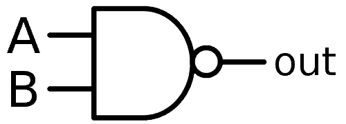
What is a NAND gate/NAND logic?
A NAND gate’s output is low only when both the inputs are high. In all the other cases, its output is high. We can obtain NAND logic by just connecting a NOT gate to an AND gate. Let’s take a look at the symbol and the truth table.
Truth table for NAND gate/operator
| A | B | Y(A nand B) |
| 0 | 0 | 1 |
| 0 | 1 | 1 |
| 1 | 0 | 1 |
| 1 | 1 | 0 |
The NAND function is sometimes also known as the Sheffer Stroke function. We can represent it as follows
Y (A nand B) = 

What is a NOR gate/NOR logic?
A NOR gate’s output is high only when both the inputs are low. In all the other cases, its output is low. We can obtain NOR logic by just connecting a NOT gate to an OR gate. Let’s take a look at the symbol and the truth table.

Truth table for NOR gate/operator
| A | B | Y(A nor B) |
| 0 | 0 | 1 |
| 0 | 1 | 0 |
| 1 | 0 | 0 |
| 1 | 1 | 0 |
The NOR function is sometimes also known as the Pierce function. We can represent it as follows
Y (A nor B) = 

Why are NAND and NOR gates known as universal gates?
NAND and NOR logic gates are known as universal gates because they can implement any boolean logic without needing any other gate. They can be used to design any logic gate too. Moreover, they are widely used in ICs because they are easier and economical to fabricate.
How to design all gates using NAND and NOR logic gates?
Using universal gates we can derive all the basic logic gates, EXOR gate, and their inverse gates. It takes a bit of trial and error. Or you can use boolean logic to obtain these. You have the equation for a NAND gate and for a NOR gate. You also have equations for the gates you wish to design. Use Boolean logic and solve for the output you need. It might take some time but it is necessary to practice this to get a hang of boolean logic and logic gates. Cross-check your designs with the designs below. In the next post, we will design some simple combinational logic circuits using logic gates.
All gates using NAND gate

- NOT using NAND: It’s simple. Just connect both the inputs together.
- AND using NAND: Connect a NOT using NAND at the output of the NAND to invert it and get AND logic.
- OR using NAND: Connect two NOT using NANDs at the inputs of a NAND to get OR logic.
- NOR using NAND: Just connect another NOT using NAND to the output of an OR using NAND.
- EXOR using NAND: This one’s a bit tricky. You share the two inputs with three gates. The output of the first NAND is the second input to the other two. Finally, another NAND takes the outputs of these two NAND gates to give the final output.
All gates using NOR gate

- NOT using NOR: It’s simple. Just connect both the inputs together.
- OR using NOR: Connect a NOT using NOR at the output of the NOR to invert it and get OR logic.
- AND using NOR: Connect two NOT using NORs at the inputs of a NOR to get AND logic.
- NAND using NOR: Just connect another NOT using NOR to the output of an AND using NOR.
- EXNOR using NOR: This one’s a bit tricky. You share the two inputs with three gates. The output of the first NOR is the second input to the other two. Finally, another NOR takes the outputs of these two NOR gates to give the final output.
Check out Derek Molloy’s videos on Youtube on using digital ICs to implement digital logic. Here’s one for AND logic implementation.
Were you able to completely grasp the concept of boolean logic and the designing of logic gates? Let us know if you felt any issues in understanding any concept so that we can try to explain it to you using a different approach. We’re always happy to get your feedback!
Sources:
Note: We will use all of the equations above when we code these logic gates using VHDL in our VLSI course.