In digital electronic systems, during data transmission and processing, data gets distorted. This is due to the noises added to it. Such noises change 0s to 1s and 1s to 0s. Annoying, right? It is necessary to identify and remove these errors.
One of the most widely used error detection techniques for transmission of data for sharing information between devices is Parity checking. In this article, we will understand the concept of using ‘parity bits‘ to detect errors in digital data. We will look at all the digital circuits (parity checkers and parity generators) involved.
This is the easiest explanation you’ll find. Read on!
Contents
What is a Parity Bit?
A parity bit is an extra bit in any binary message to make the total number of 1’s either odd or even. We need to add the parity bit to a signal. This is done by the Parity generator. This parity inclusive binary message then transmits from transmitter to receiver end.
The Parity Checker matches the number of 1’s at the receiver’s end with that of the transmitter’s end to check for errors. If there is a change in the number of 1s at the receiving end, then that detects the presence of an error.
What is even parity and odd parity?
Even parity is the case when the total number of 1s in the sum of data bits and parity bits is even whereas, in odd parity, it is odd.
What is the main concept behind using parity bits for error detection?
Here’s the main concept behind parities. Remember this. The binary sum of an even number of 1s is 0. And the sum of an odd number of 1s is 1. That’s a fact.
Now imagine a scenario. You want to send a stream of digital bits. Let’s say that this stream has n bits. You are slightly concerned with errors entering your message. So you say, “Hey! I need to use some kind of error detection mechanism”. So you decide to use ‘parity bits.’ Now you have two choices. You can either use the even parity mechanism. Or you can use the odd parity mechanism.
Even parity mechanism: The target is to make the total number of 1s even. For example, if you have a message signal “010”, you can clearly see that it has just one 1. So we add a parity bit to make it two 1s. Now the number of 1s is even.
Odd parity mechanism: Here, the target is the make the total number of 1s odd. For example, consider the same message signal from above. “010”. The parity bit here will be….complete the sentence. 0! That’s right. There’s already an odd number of 1s in the message signal.
Notice one thing? In this error detection method, the final message is the message you intended to send, plus one parity bit.
Final message = Message signal + parity bit
When the message reaches the destination, all we need to check is the parity bit if it is odd or even parity. Cross-reference that with what we knew at the transmitting end. And we can detect if an error is present. Next, we will design some good lookin’ circuits to carry out this whole process.
What is the difference between a Parity Generator and a Parity Checker?
You can probably guess it by now. But for the sake of clarity, I’ll mention it. The primary difference between parity generator and a parity checker is that a parity generator is a combinational logic circuit we use in the generation of the parity bit. On the other hand, a parity checker is a circuit that checks the parity (number of 1s) of the message signal.
Both these circuits are located at different sites based on their working. A parity generator is present at the transmitter end to generate the parity bit. Later it combines with the message signal. The Parity checker is present at the receiver end for error detection through parity bit count.
How does a Parity Generator work?
Assume that your final message is an n-bit stream of digital data. One of the bits is the parity bit. To transmit this bitstream containing n-1 data (message signal) plus one additional parity bit, we require a special circuit known as parity bit generator. The parity generator is a combinational logic circuit.
The parity generators can create two parities. Even parity generates a final message with an even number of 1s. So the parity bit for an even number of 1s is 0. On the other hand, an odd parity bit generates when the total number of 1s in the bitstream is odd.
Even parity Generator
3 bit Even Parity Generator:
Suppose at the transmitting end, and we have a 3-bit message signal that we wish to transmit using an even parity bit. Let A, B, and C be input bits and P be output that is even parity bit. Even parity generates as a result of the calculation of the number of ones in the message bit. If the number of 1s is even P gets the value as 0, and if it is odd, then the parity bit P gets the value 1. Following is the truth table for 3-bit even parity generator.
3-bit even parity generator truth table
|
3 Bit Message |
Even Parity Generator | ||
|
A |
B | C | P |
|
0 |
0 | 0 |
0 |
| 0 | 0 | 1 |
1 |
|
0 |
1 | 0 | 1 |
|
0 |
1 | 1 |
0 |
| 1 | 0 | 0 |
1 |
|
1 |
0 | 1 |
0 |
|
1 |
1 | 0 |
0 |
|
1 |
1 | 1 |
1 |
Solving the truth table for all the cases where P is 1 using Sum-of-Products method:

This expression can be implemented using two Ex-OR gates.
3-bit even parity generator circuit
Remember that this circuit is just generating the parity bit. The complete signal is a combination of the message signal and the parity bit.

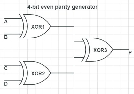
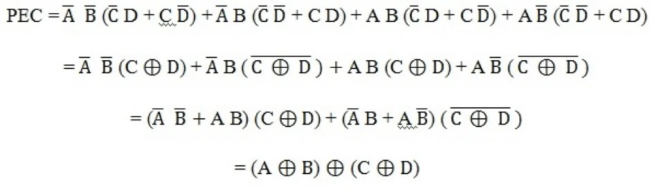
4 bit Even Parity Generator
Now suppose as, in the previous example, we have four input bit message signals instead of 3. Then the parity bit, which generates at the output end P, is as a result of A, B, C, D that are the input bits of the message signal.
4- bit even parity generator truth table
Solving the truth table for all the cases where P is 1 using Sum-of-Products method:
P = A ⊕ B ⊕ C ⊕ D
4-bit even parity generator circuit
Odd Parity Generator
3-bit Odd Parity Generator
Suppose at the transmitting end now we have a 3-bit message signal, and we wish to transmit it using odd parity. Then, the parity bit generated, P, would be as a result of odd parity generation. The total number of 1s in the input bits must be odd for the odd parity bit. If the total number of 1s in input bits is odd, then P gets the value 0, and if it is even then, P is assigned the value 1.
3-bit Odd Parity Generator truth table
| 3 Bit Message | Odd Parity Bit Generator | ||
| A | B | C | P |
| 0 | 0 | 0 | 1 |
| 0 | 0 | 1 | 0 |
| 0 | 1 | 0 | 0 |
| 0 | 1 | 1 | 1 |
| 1 | 0 | 0 | 0 |
| 1 | 0 | 1 | 1 |
| 1 | 1 | 0 | 1 |
| 1 | 1 | 1 | x |
Parity Generator VS Parity Checker
Solving the truth table for all the cases where P is 1 using Sum-of-Products method:
P = A ⊕ B Ex-NOR C
3-bit Odd Parity Generator circuit

4 Bit Odd Parity Generator
In place of 3 input bits in the message signal, if we have 4 bits, then it becomes a 4-bit odd parity generator. Now the output odd parity bit would be decided on the basis of 4 input bits, namely A, B, C, and D.
4-bit odd parity generator truth table
Solving the truth table for all the cases where P is 1 using the Sum-of-Products method. We can also use K-maps to solve for the output.
P = A Ex-NOR B Ex-NOR C Ex-NOR D
The 4-bit odd parity generator circuit

How does a Parity Checker work?
A parity checker is a logical circuit that checks data transmission errors. Based on the type of parity generated, it can be even a parity checker or odd parity checker. The number of inputs must be even for even parity checker and odd for odd parity checker. If a parity error occurs, the “even” output goes low, and “odd’ output goes high in case of even parity checker. It is the other way round for odd parity checker.
Even Parity Checker
3 Bit Even Parity Checker
Suppose at the transmitting end, even parity bit is generated, and we have three input message signals and one parity bit. The parity checker circuit is fed all these four bits to check for possible errors. So a 3-bit parity checker actually has a 4-bit input.
Since the transmitting end is working with even parity, the number of 1’s at received by the checker circuit must be even. For every case, where the input to the parity checker has an odd number of 1s, the error output will be 1.
This high error output indicates that an error is present in the signal. And for every input where the number of 1s is the expected even count, the error output will be 0.
3 Bit Even Parity checker truth table
| 4 Bit Received Message | Parity error check Cp | |||
| A | B | C | P | Cp |
| 0 | 0 | 0 | 0 | 0 |
| 0 | 0 | 0 | 1 | 1 |
| 0 | 0 | 1 | 0 | 1 |
| 0 | 0 | 1 | 1 | 0 |
| 0 | 1 | 0 | 0 | 1 |
| 0 | 1 | 0 | 1 | 0 |
| 0 | 1 | 1 | 0 | 0 |
| 0 | 1 | 1 | 1 | 1 |
| 1 | 0 | 0 | 0 | 1 |
| 1 | 0 | 0 | 1 | 0 |
| 1 | 0 | 1 | 0 | 0 |
| 1 | 0 | 1 | 1 | 1 |
| 1 | 1 | 0 | 0 | 0 |
| 1 | 1 | 0 | 1 | 1 |
| 1 | 1 | 1 | 0 | 1 |
| 1 | 1 | 1 | 1 | 0 |
If the four-bit received message consists of an even number of 1 means, no error has occurred. If it contains an odd number of 1 means, an error has occurred.
Even parity checker for three input message signals and even parity bit can be implemented with three EX-OR Gates.
3 Bit Even Parity checker circuit

Odd Parity Checker
3 Bit Odd Parity Checker
Suppose at the transmitting end odd parity bit is generated, and we have three input message signal. The parity checker circuit is fed all these four bits to check for possible errors. Since the transmitting end is working with odd parity, the number of 1’s at received by the checker circuit must be odd.
An error occurs on the even number of 1’s at the receiver’s end; that is, the message signal has become distorted.
3 Bit Odd Parity Checker truth table
| 4 Bit Received Message | Parity error check Cp | |||
| A | B | C | P | Cp |
| 0 | 0 | 0 | 0 | 1 |
| 0 | 0 | 0 | 1 | 0 |
| 0 | 0 | 1 | 0 | 0 |
| 0 | 0 | 1 | 1 | 1 |
| 0 | 1 | 0 | 0 | 0 |
| 0 | 1 | 0 | 1 | 1 |
| 0 | 1 | 1 | 0 | 1 |
| 0 | 1 | 1 | 1 | 0 |
| 1 | 0 | 0 | 0 | 0 |
| 1 | 0 | 0 | 1 | 1 |
| 1 | 0 | 1 | 0 | 1 |
| 1 | 0 | 1 | 1 | 0 |
| 1 | 1 | 0 | 0 | 1 |
| 1 | 1 | 0 | 1 | 0 |
| 1 | 1 | 1 | 0 | 0 |
| 1 | 1 | 1 | 1 | 1 |
If the four-bit received message consists of an odd number of 1 means, no error has occurred. If it contains an even number of 1 means, an error has occurred.
E = (A Ex-NOR B) Ex-NOR (C Ex-NOR D)
Odd parity checker for three input message signal and odd parity bit can be implemented with three EX-NOR Gates.
3 Bit Odd Parity Checker circuit

Sum even and Sum odd
Here’s an important yet confusing thing you need to remember. Parity checking circuits have two additional outputs. ‘Sum even’ and ‘sum odd.’ These outputs are basically signals that tell an observer if the message received is error-free or not. The confusion arises from the fact that they have their meanings switched for odd and even parity checkers.
For even parity checkers: If an error occurs, Sum even = 0 and sum odd = 1. The desired output (even) goes low in case of error.
For odd parity checkers: If an error occurs, Sum even = 1 and sum odd = 0. The desired output (odd) goes low in case of error.
Parity Generator/Checker ICs
Plenty of ICs with different input configurations are available today on the market, such as 4 bit, 5 bit, 9 bit, etc. The most commonly used standard type being IC 74180.

This IC 74180 is a 9-bit parity generator, and checker especially used to detect errors in high-speed data transmission and retrieval systems. It is used to generate both even and odd parity.
The IC consists of 8 message signal bits from A to H and two cascading inputs for even and odd. It has two outputs. Even sum and odd sum. For the proper implementation of generator/checker, unused parity bit must be tied to logic zero, and the inputs must not be equal.
Were we able to explain the concept of parity generators and parity checkers successfully? If you have any queries, make sure to let us know, and we will get back to you. Meanwhile, check out our digital electronics course for more.