The ESP8266 Wi-Fi module is a nifty little device that has enabled tinkerers to connect their projects to the internet at a very reasonable cost. It is one of the easiest methods of adding Wifi functionalities to your Arduino. Just to remind you, Wifi is only one of many communication protocols. There are many other ways of wirelessly communicating with an Arduino. However, wifi is simple, everyone understands it, and it’s accessible. So without any further ado, let’s begin with interfacing an ESP8266 module with an Arduino Uno.
Contents
Why should we interface the ESP8266 Wi-Fi module with Arduino?
Today we communicate with each other using mobile phones, which is a wireless communication device. It helps us to communicate with our friends at any place and at any time. How about sharing a data to a machine from a distance wirelessly. It is possible by using this ESP8266 – Wi-Fi module. The crux of the matter is accessibility. The current trends in the IoT sector ask for control over the internet. And Wifi is a leading facilitator of that feature.
What is the ESP8226 Wi-Fi module?

The ESP8226 is a low-cost Wi-Fi microchip with a fully functional Wifi and TCP/IP protocol stack that can give any microcontroller access to your Wi-Fi network. This can enable you to either host an application on your device or offload all Wi-Fi networking functions from another application processor.
Each ESP8266 module comes with pre-programmed AT command set firmware that you can simply hook this up to your Arduino device and get about as much Wi-Fi ability. These AT commands are special instructions that you can use to work with the ESP8266’s onboard microcontroller easily. However, when you use it with an Arduino, this default firmware gets replaced. We will take a look at the AT instructions in detail in a later post in our Arduino course.
What are the components required for the ESP8266 Wi-Fi module interfacing with Arduino?
In this article, we are going to control an LED over wifi using the ESP8266. The hardware requirements are listed below:
- Arduino Uno
- ESP8266 Wi-Fi Module (ESP-01)
- 1 x LED
- A Push Button
- Resistors: 330 Ω, 1 KΩ, 2 KΩ.
- Breadboard.
- Jumper wires – as required.
- Arduino Uno
- ESP8266 Wi-Fi Module (ESP-01)
- 1 x LED
- A Push Button
- Resistors: 330 Ω, 1 KΩ, 2 KΩ.
- Breadboard.
- Jumper wires – as required.
Understanding the ESP8266 Arduino Wi-Fi module
The ESP8266 is a user-friendly low-cost device that provides internet access to your project. We will now understand a few features and specifications of this module. It is necessary to truly understand the capabilities of an Arduino shield or module you use. This practice will help you imagine new use cases and improve your journey of learning the Arduino environment.
Internal circuit of ESP8266

It has two LEDs. The red one indicates whether it’s on. And the blue one is for indicating data transmission
Features of ESP8266
- It has 32- bit microcontroller
- CPU: 80 MHz (default) or 160 MHz
- Memory: 32 KiB instruction RAM, 80 KiB user data RAM, 32 KiB instruction cache RAM, 16 KiB ETS system – data RAM.
- Input: 16 GPIO pins
- Processor: L106 32-bit RISC microprocessor core based on the Tensilica Xtensa Diamond standards 106 Micro running at 80 MHz.
- External QSPI flash: up to 16 MiB is supported (512 KiB to 4 MiB typically included)
- The new version of the ESP8266 Wi-Fi module has increased the flash disk size from 512KB to 1MB.
- IC (software implementation)
- IS interfaces with DMA (sharing pins with GPIO)
- 10-bit ADC (successive approximation ADC).
Dimensions of ESP8266
ESP8266 module dimension: 24.75mm x 14.5mm (0.974″ x 0.571″)

Working of ESP8266
The ESP8266 is a UART-Wi-fi module that can be controlled from your local network or the internet. It is a device that uses wi-fi technology to send and receive data wirelessly. It uses radio-wave frequencies to send and receive data. ESP8266 can work both as an access point and also as a station.
Wi-Fi is a family of radio technologies commonly used for wireless local area networking (WLAN) of devices. Wi-Fi is abbreviated as “Wireless Fidelity.” It uses radio waves to provide network connectivity without the use of any cables or wires. Notably, It must have three components that are radio signals, antenna, and router.
We can use it as a standalone device since it comes with its own microcontroller. Or we can pair it with other platforms like the Arduino Uno and the Raspberry Pi. In this particular tutorial, we will be controlling the ESP-01 (A variant of the ESP8266) using an Arduino Uno.
The ESP-01 module sort of forms a gateway between the Arduino and the internet. It acts as a hub that receives data/instructions sent over WiFi and then sends this data to the Arduino. Thereby taking your Arduino online. The antenna transmits the radio waves, and inbound signals are taken up by Wi-Fi receivers. Therefore, it can communicate with both 2.4 GHz devices and 5 GHz devices.
ESP8266-01 Boot Option
GPIO – 0 pin |
GPIO – 2 pin |
Mode |
Usage |
| High | High | Flash-Mode | Run the program that is already uploaded to the module |
| Low | High | UART Mode | Programming mode- used for writing a program using Arduino or any serial communication |
Pins of ESP8266
The pinout of the ESP-01 and the corresponding functions of the pins are shown below.

Pin no |
Name |
Description |
| 1 | VCC | Voltage (+ 3.3 V it can handle up to 3.6 V) |
| 2 | GND | Ground (0V) |
| 3 | RX | Receive data bit X |
| 4 | TX | Transmit data bit X |
| 5 | CH_PD | Chip power-down |
| 6 | RST | Reset. This is an active-low pin. |
| 7 | GPIO 0 | General-purpose input/output No. 0. The ESP8266 has two modes: Programming mode and Normal mode. In the programming mode, we upload code/firmware to the device. In Normal mode, we use it for its intended purpose. To enable programming mode, this pin needs to be connected to GND first. |
| 8 | GPIO 2 | General-purpose input/output No. 2 |
The circuit diagram to interface ESP8266 with Arduino Uno
For this experiment, you need to interface the ESP8266 Wi-fi module with your Arduino via the serial communication ports. This is because the ESP-01 communicates using serial communication protocols. Remember what we learned about two communicating devices using the same protocols in the Arduino communication protocols post. Thus, we need serial communication from the Arduino end too. Thus we use the TX and RX pins available on the Arduino Uno. You can learn more about the various pins of the Arduino Uno here.
Check out the circuit diagram below to hook up your ESP8266 (ESP-01) with the Arduino Uno.
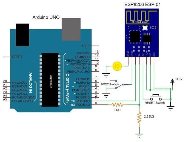
- Connect digital pin 2 (D2) of the Arduino with the RX of the ESP8266
- Connect digital pin 3 (D3) of the Arduino with the TX of the ESP8266
- You can use a level connector circuit for regulating the voltage at transmitter and receiver pins. A level converter is necessary at the RX pin connection from the Arduino.
- You can connect a 1KΩ resistor at the transmitter pin and also a 2.2Ω resistor at the receiver pin of the ESP8266.
- An LED is connected with the D11 pin of the Arduino board.
- The input power supply should be 3.3 V, so connect the Vcc pin of the ESP8266 with the 3.3V Vout pin of the Arduino. Similarly, connect the ground pin with GND pin of the Arduino
- You can connect a push button between RESET of ESP8266 and GND.
- Both GPIO pins of the Wi-fi module (GPIO0 & GPIO2) are not used in this experiment.
Arduino programming to connect the ESP-01 with the Arduino Uno
You will need a library file ESP8266Wifi.h for interfacing the ESP8266 with your Arduino. You can find out more about handling and installing libraries in the Arduino IDE here.
Arduino programming is done in the Arduino environment. Not necessarily, though, you can install CodeBlocks to work with your Arduino too. But that’s a whole other can of worms that you should keep from opening at this stage.
First, we need to connect the Arduino environment with our Arduino Uno board by selecting a suitable port.
The Arduino code should contain two functions as void setup() and void loop(). All pin-mode declarations are made in void setup(). And the function to be performed and the computing process is coded in void loop(). For a revision to Arduino programming, you can check out our ultimate programming tutorial for the Arduino Uno here.
Code for interfacing an ESP8266 with an Arduino Uno
The code helps you to interface the ESP8266 Wi-fi module with your Arduino and commands ESP8266 to receive the data that is sent by the client. Then the Arduino will control the LED according to the instruction.
#include <ESP8266WiFi.h>
const char WiFiPassword[] = "LED12345";
const char AP_NameChar[] = "LEDControl" ;

WiFiServer server(80);

String header = "HTTP/1.1 200 OK\r\nContent-Type: text/html\r\n\r\n";
String html_1 = "<!DOCTYPE html><html><head><meta name='viewport' content='width=device-width, initial-scale=1.0'/><meta charset='utf-8'><style>body {font-size:140%;} #main {display: table; margin: auto;  padding: 0 10px 0 10px; } h2,{text-align:center; } .button { padding:10px 10px 10px 10px; width:100%;  background-color: #4CAF50; font-size: 120%;}</style><title>LED Control</title></head><body><div id='main'><h2>LED Control</h2>";
String html_2 = "<form id='F1' action='LEDON'><input class='button' type='submit' value='LED ON' ></form><br>";
String html_3 = "<form id='F2' action='LEDOFF'><input class='button' type='submit' value='LED OFF' ></form><br>";
String html_4 = "</div></body></html>";

String request = "";
int LED_Pin = D1;

void setup()
{
    pinMode(LED_Pin, OUTPUT);

    boolean conn = WiFi.softAP(AP_NameChar, WiFiPassword);
    server.begin();

}


void loop()
{

    // Check if a client has connected
    WiFiClient client = server.available();
    if (!client)  {  return;  }

    // Read the first line of the request
    request = client.readStringUntil('\r');

    if       ( request.indexOf("LEDON") > 0 )  { digitalWrite(LED_Pin, HIGH);  }
    else if  ( request.indexOf("LEDOFF") > 0 ) { digitalWrite(LED_Pin, LOW);   }

    client.flush();

    client.print( header );
    client.print( html_1 );
    client.print( html_2 );
    client.print( html_3 );
    client.print( html_4);

    delay(5);
  // The client will actually be disconnected when the function returns and 'client' object is detroyed

} // void loop()
Upload this code and connect to the ESP8266 using your mobile phone’s wifi. The password is LED12345. Next, open a browser on your phone and connect to the ESP8266 using the IP address 192.168.4.1. You can also find the IP address of your Wi-fi module using a tool called Advanced IP scanner. Then find the module’s IP address using this tool and insert this IP address in the webpage IP address bar.
Here’s the HTML code for the web app.
<head>
<meta name="viewport" content="width=device-width, initial-scale=1.0"/>
<meta charset="utf-8">
<style>
body {font-size:140%;}
#main {display: table; margin: auto;  padding: 0 10px 0 10px; }
h2,{text-align:center; }
.button { padding:10px 10px 10px 10px; width:100%;  background-color: #4CAF50; font-size: 120%;}
</style>
<title>LED Control</title>
</head>
Now you can control the LED by touching on/off button on your webpage.
You can also control any other devices using this same procedure and also via the internet from anywhere.
Moreover, you can also control the ESP8266 Arduino Wi-fi module using AT commands. Whereas, You can do it without any extra-configurations,
Few basic AT commands are listed below,
- AT – response OK
- AT+CWLAP-It will let you know nearby Wi-fi networks
- AT+GMP- Using this you can check the firmware version
- AT+CWJAP- Let you join with the Wi-fi network using “<access point name>,””<password>.”
- AT+CIFSR- Let you know to get the currently allocated IP address.
There are many AT commands available. We will look at controlling the ESP8266 using AT commands at a later stage.
Common problems and troubleshooting when connecting the ESP8266 with the Arduino Uno
The ESP8266 module is not capable of 5-3V logic shifting and will require an external logic level converter. You have 5V and 3.3V power out features available on your Arduino Uno, as we saw in this post on the Arduino power supply. However, it is highly advised to use a separate 3.3V source for the ESP8266.
To communicate with the ESP8266 via the Arduino Uno. Make sure the RX connects to the TX, and the TX connects to the RX. If you wish to communicate via the ESP8266, then RX-RX and TX-TX connection work.
Applications of the ESP8266
ESP8266 has a wide range of applications in IoT based projects. Hence, some cool applications are listed below,
- You can turn On /Off any device using Windows remote Arduino.
- Wi-Fi controlled remote car.
- Home management system.
- Drone control.
- Smart house applications.